
I’ve spent a significant portion of my engineering career navigating industrial metals, electroplating processes, and precision tools for electronic manufacturing. In that time, the comparison between die base alloys and copper cathodes kept surfacing in material science discussions—particularly when dealing with applications like circuitry plating, tooling molds, or even base trim molding operations. I'll walk you through both technologies, share some first-hand technical insights, and break down how each is used in real-world industrial and electrical environments.
Copper Cathode vs. Die Base: The Big Picture Overview
To start out—I’ve encountered many engineers who mistakenly interchange these materials in early designs because they both play important roles in electroplating and metalworking, but their functions are drastically different. A **Copper Cathode** serves mainly as a pure form of source copper during electrolytic refining, especially important for industries needing ultra-high conductivity copper wire production.
In comparison, what people sometimes label generically as a *die base*, actually points to mold frames or structural supports within high-precision casting or injection processes—for instance, used extensively during Base Trim Molding for building panels. These two components may intersect indirectly (say, when tin coating over copper involves tool holders or clamps crafted from die bases), but they remain functionally independent pieces within the workflow chain.
Diving into Die Bases – What Are They Really Made Of?
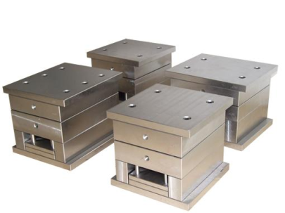
Lately, the topic “What exactly constitutes a proper die base?" has been on several of our workshop Q&A boards at plant level meetings, probably triggered by the uptick in customized mold projects we’ve rolled out last quarter. Traditional die bases can range from pre-hardened steels (like S45C or SCM435) up through specialized tool steels such as P20 or even more exotic options when higher tolerance is non-negotiable.
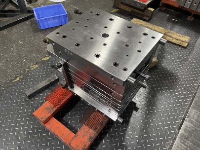
The critical properties of a solid die base include wear resistance and structural stability—because these frames need to bear immense compression forces across thousands of injection cycles without losing dimensional accuracy. When someone says they’re designing a "trim" for molded casing covers—what they’re often referencing is mounting it into a machined die support structure before cutting excess material—yes, related quite tightly to *base trim molding*
- Dies often fabricated from multi-alloyed aluminum blends if faster thermal conductivity is preferred over longevity
- Benchmark specs favor minimal deformation (< 1μm/cm²) under operational temps of ~75–220°C for thermoplastics processing.
- Precise guide rail alignment systems ensure mold cores open without shearing edge fractures during part release stages
Electrochemical Use Cases – Why You Need Copper Cathodes
You can't beat an ultrapure copper cathode when sourcing raw feedstock ions. Electroplating tanks rely on sheets made from SX/EW (Solvent extraction electrowon) or blister-derived copper forms because any trace impurity will cause irregularities once the copper atoms deposit onto substrates.
In fact—if you’ve ever struggled figuring out ‘how to tin plate copper,’ the first key point hinges precisely on using quality base material. Because no matter the flux type or temperature ramp-up curve in solder immersion baths—if your original substrate is uneven in purity due to flawed initial plating layer...your results will reflect that unpredictability.
| Attribute | Copper Cathode | Tin Anodes/Strips |
|---|---|---|
| Purity Standard | min 99.95% | Near-grade: ~98–99.2%, dependent on use-case tolerance margins |
| Melting Temperature (Avg) | 1083 °C | About 232°C – allowing easy overlay coatings atop copper layers |
| Applications | Cable & bus bar core plating; semiconductor heatsinking pads; EDA circuits | OEM auto-wires; consumer appliances terminals; PCB through-hole metallization prior RoHS bans shifted industry toward OSP+Immersion Sn standards |
How to Tin Plate Copper Without Fuss—Lessons Learned in Field Operations
Honestly—figuring ‘how to tin plate copper‘ correctly the first run took me months of back-and-forth tweaking between bath parameters and surface etch preparation strategies in pilot testing. The trick? Start by chemically activating the surface via sulfuric-peroxide microetch slurry followed by immersion cleaning steps that eliminate carbon films left by handling gloves or machine oil residue—trust me on this step alone saving hours of do-over dips later down the day’s schedule!
Here are three techniques that proved rock-solid during multiple line expansions:- Anolyte agitation maintained between 12-18 AFT depending cell volume—never stagnant conditions allowed
- Cathode moving speed set precisely around .015 mm/sec for smooth dendrite control across large panel areas (anything aggressive would spike burr formations increasing rejection ratios at QA)
- Rinse stages integrated inline immediately post-coating; hot DI spray rinse above 65°C helps prevent hydroxide buildup spots while ensuring fast drying ahead of pack-off conveyors
Why Compatibility Between Tools, Materials, and Process Standards Matters Most
We’ve found in past R&D sprints—even seemingly separate concepts such as *base trim molding jigs* or die frame calibration must match upstream plating uniformity demands. For example—we tried using standard plastic trimming heads designed for acrylic panels on epoxy-based circuit board resin carriers one week, and guess what happened next shift? The CNC spindle overloaded thrice within two hours because of unaccounted composite fiber stiffness factors affecting bit wear rates exponentially compared to our original trial runs on polyethylene substrates.
Conclusion & Key Takeaways
- Die Base Alloys: Must be engineered considering stress resistance over repetitive load bearing scenarios typical in long-run injection cycles or automated press-fit tooling applications.
- Copper Cathode: Your baseline for electroforming, conductive pathways in hybrid IC design, and stable sacrificial electrodes where purity guarantees process yield consistency.
☑️ Low porosity plating essential
✔️ Structural longevity
✔️ Mold cavity sealing capability
This isn’t some lab paper written for publication purposes only; every data point discussed came directly from production floor analysis reports, maintenance log reviews—or frankly—costly equipment burn-in mistakes from my time managing Tier 2 suppliers across APAC electronics zones
“Even after hundreds of production cycles—you can’t expect predictable tinning efficiency without verifying the entire system's interdependence."
— Lead Manufacturing Advisor @ Precision Metallurgical Inc.