
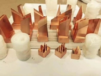
For any foundry professional, casting raw copper blocks can quickly transition from a standard process to an operation filled with variables if your equipment setup lacks attention — especially when it comes to the die base selection. As someone who’s cast countless molten pours and messed up early attempts due more than just heat regulation problems; selecting an improperly constructed or mismatched die base was often a core issue I came back to. Let me break down my hands-on experience in choosing not only any functional option but *the* correct Die Base to optimize performance.
Evaluating Material Compatibility Between Die Base And Raw Copper Blocks
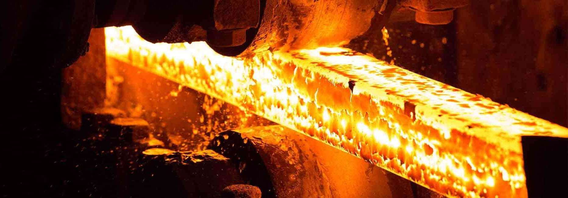
Casting anything starts well before flame meets ore. With Raw copper block production though, temperature stability isn't optional - this is particularly true once you get into consistent, industrial output volumes. Your typical aluminum alloys might suffice at first glance for temporary use but over longer periods thermal degradation will warp them beyond usability—especially with larger format copper billets.
- Certain tool steels like H13 maintain form through hundreds of casting runs even near melting points exceeding 1085 C
- Brass inserts within a graphite-impregnated mold can help with minor surface finishes (great for low-volume prototype batches too!)
Material Average Conductivity
(@30°c avg)Durability Level 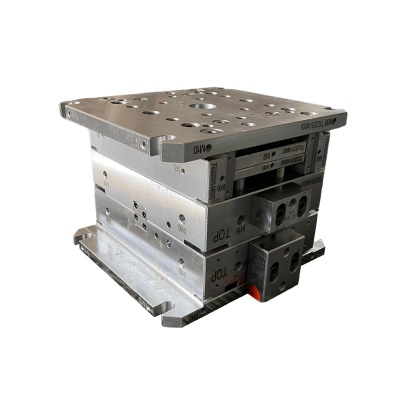
Graphite-Carbon Composite
![[Image Description]](//upload.wikimedia.org/wikipedia/commons/thumb/7/74/Lab_conical_graphite_crucible_%2C_opening.jpg)
- Thermal Conductor Rating : ★★★★☆
- Heat Transfer Efficiency High
Fair Tool Steel(H13) Medium conductivity
*Ideal for high cycle castingExcellent Long term durability Vinyl-Coated Steel Alloy Very Low - Insulated properties dominate Poor - Recommended mostly as test fixtures - If you’re working on precision-based architectural components requiring ultra smooth surfaces later; invest in a pre-polished die core with micro-grinding finish specs down to Ra=0.8 µin average roughness
![[Image Description]](http://upload.wikimedia.org/wikipedia/commons/thumb/7/74/Lab_conical_graphite_crucible_%2C_opening.jpg)
Determinining The Core Shape Geometry That Fits Best Into Your Mold Flow Process
TroubleShooting Issues When Applying & Removing Wax In Preparation Stage Of Pouring
- Routinely clean out all die base crevices between every third batch (more frequently when higher impurity levels present in source ore feedstock )
- Warm up mold sections slightly above 50°C for paraffin applications instead applying straight onto cold metal—it spreads more fluidically, covers finer contours and reduces porosity issues later.
-
Always dry wipe off wax layer after demold rather than aggressive chipping methods: Chipped surfaces aren’t only unsightly visually—they risk compromising future pour accuracy via pitted spots.
- Use specialized mold-release sprays rated for metallic alloys specifically, especially when planning reuse cycles upwards past ten consecutive uses—regular silicon blends don’t withstand thermal fluctuations effectively and degrade faster
| Mold Cross-section Shape | Ideal Usage Type |
|---|---|
| Ridgid Rectangular Profile Molds | Larger Structural Support Blocks For Electrical Systems / Transmission Infrastructure |
| Semi-rounded Hex molds | Cable Jacket Production Lines Where Heat Dissipation Matters Significantly Over Extended Time Periods |
| Curved Oval Bases With Internal Rib Structures | Ideal for casting smaller weight batches that prioritize fast ejection times during multi-shift operations. Note: These also prevent sticking after long cooling cycles better than flat sided versions |