
The Best Practices for Choosing and Using Copper Blocker in Mold Base Construction for Injection Molding Efficiency
Over the last couple years, I've spent hundreds—if not thousands—of ours working in injection molding shops. And if there's one thing that consistently pops up during mold construction: proper heat management around ejector pins. Enter copper blocker plates, more specifically, copper blockers made of 1OZ Copper material. In this article, we'll go into some real-deal insights I've personally picked up using copper blocking systems within my mold bases, why I think it matters more than most give credit, and how to make copper plates that stand the test of production use (and operator error).
What is a Copper Blocker, Really?
You're likely asking, what even *is* copper blockage here? Let me break it down for you.
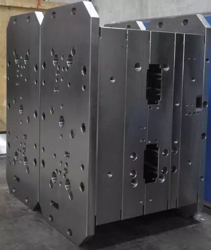
- A copper blocker, simply put, sits in the cavity between moving mold components like the rear support plate and the backrest plate, preventing conductive thermal distortion through metal transfer pathways.
- The idea? Minimize unnecessary heat retention by blocking the natural flow between mold base elements using something with lower conductivity than typical tool steel — say, OFHC copper, which is typically used as 'copper blocker.'
Quick tip from personal exprience: Never assume standard mild steel spacers will cut it when you start getting into high-cavity runs that see 50K cycles and beyond per mold set-up.
Why Should You Even Care About Thermal Transfer Here?
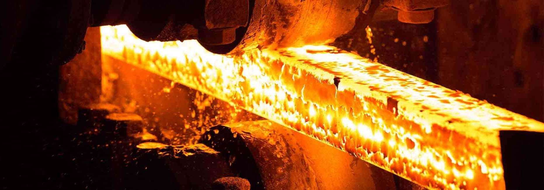
Copper blockers may sound overengineered but trust me, ignoring this element in your mold base will bite you somewhere on cycle count 30-40k depending how aggressive your molding parameters are. The main reason being: excessive heat builds in unintended areas, mostly behind cavity blocks or cooling inserts near slide assemblies.
| Mold Area Affected Without Copper Blocker | Common Symtoms / Failures Seen Over Time |
|---|---|
| Ejector Housing | Heat fatigue & pitting, uneven wear |
| Pilot Ejector Pins | Binding during ejection |
| Baffle Coolant Systems | Fouling inside lines due to overheating fluid path |
You're not saving cost by cutting corners—your downtime bill and re-machining expenses might skyrocket instead.
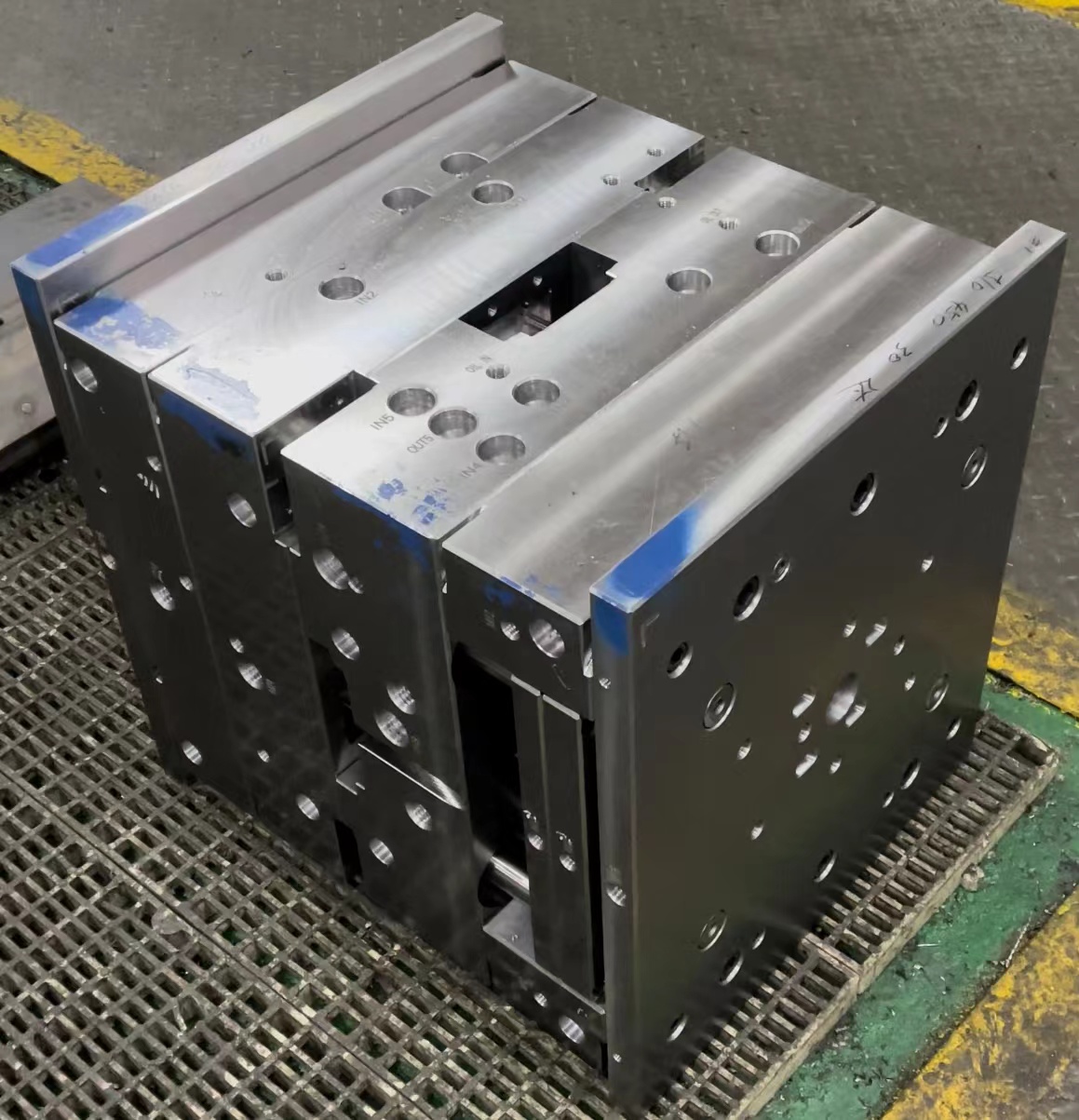
To give context: I saw a team try to bypass traditional **copper blocker placement** thinking modern steels would be enough—and yeah… after 10 days of continuous run time on a high-temp polyetherimide job, the backer plate warped so severely they had to pull it off and grind .300" down just to get squareness back under spec again. Yeah, I won't forget those red flag warnings.
Selecting the Right Kind of Copper – Not All 1OZ Copper Is Equal
If there's one area people mess this whole equation uo, it's here. They confuse “1OZ Copper" as interchangeable across all copper plating scenarios—but let me stop this rumor before it spreads wider than my last Instagram post did. There’s a difference here and it's worth understanding:
- Straight Sheet OFHC Cu (UNS C10100): This type of soft oxygen-free copper has almost no oxide inclusion meaning better conformal fit under pressure—great as dielectric barrier in tight mold setups. Also excellent solder wetting ability—important in EDM applications where spark gap can damage surrounding base material integrity overtime if left unshielded
- “Electroplated" copper foil at ‘equvalient’ oz thickness usually doesn’t mean physical density equivalence in same layer weight measurement—it often ends up much thinner when milled to final dimensions. Be warned, don’t substitute based strictly upon listed surface coverage value!
Here’s my non-negotiation: Only go OEHC sheet product rated 0.8 -1mm actual physical gauge unless specified differently for custom applications via CAD analysis.
My Own Technique on How to Make Copper Plates for Industrial Application
This isn't your typical "step-by-step manual," it’s the method developed out of trial, lots of failure, plus one melted hand-held shear from an improperly clamped blank I tried to punch too quickly... long story short: don't skip this section!
The Cutting Process: Laser vs Saw?
- I always choose fine kerf lasers these days because copper is super easy to warp with mechanical shear stresses. Especially if we’re looking at any geometry beyond rectangle profiles.
Note: For thin 1 mm foils you can get by wih water jet. But anything over than, stick with CO2 lasers under 3.5 kW maximum energy output settings - Saw blades dull extremely fast with soft copper; microburrs form along edges leading edge misalignment when inserted manually without de-burring step afterward.