
Choosing the Right Copper Bar for Die Base Manufacturing Applications
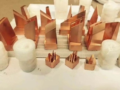
In today’s demanding industrial sector, I've often wrestled with choosing materials that balance conductivity, machinability, and durability—especially when dealing with die base components. For complex molds or heavy-duty dies in manufacturing setups, I found copper bars emerging as one of the most promising solutions.
Copper bars bring several benefits including high thermal resistance, ease of fabrication, and superior electrical characteristics, which align well in precision-driven sectors like injection molding or progressive metal stamping. My early exposure to substandard aluminum-based alternatives made this decision all the more evident over time.
| Material | Tensile Strength (psi) | Thermal Conductivity BTU/(hr.ft.°F)) | Machining Ease |
|---|---|---|---|
| Bare Copper Bar | 30,000–60,000 | ~228–235 | Ease |
| Aluminum | 9,000–75,000 | ~140–130 | Moderate |
| Ductile Iron | 60,000–150,000 | ~20–32 | Harder |
- Copper doesn't warp easily even under thermal pressure.
- I’ve observed lower tool abrasion on CNC cutters with these alloys over standard steel equivalents.
- Dimensional tolerance can sometimes require rethinking design margins depending on cooling dynamics needed.
Understanding the Advantages of Bare Copper Wire Compatibility in Mold Making Tools
If there’s something I overlooked during an assembly upgrade once was cross-referencing bare copper wire compatibility. I discovered a mismatch between insulation coatings in certain electrical discharge machining (EDM) wires versus contact surface conductivity through my trial batches—which caused irregular erosion spots during electrode work.
To ensure your systems operate consistently you’ll likely want conductors matched to any copper-enriched bases—this ensures clean transfer paths without voltage losses across mold surfaces, especially important where precision down to thousandths of an inch matters.
- Evaluatw your machine specifications for recommended EDM electrodes.
- Note thermal dissimilarity in joint areas if different metals used side-by-side.
- Cross-check conductivity curves vs temperature charts before production starts .
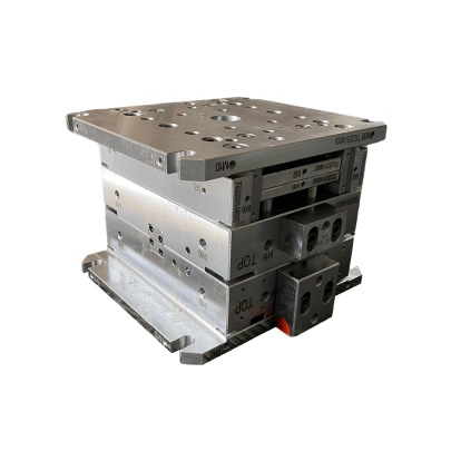
Installation Challenges with Large Die Sets Using Pure Metal Inlays
Back in ’21, handling an automotive transmission part press line installation nearly derailed because we misestimated expansion rates when integrating copper elements inside iron-dominant frames. While die basesmaintained dimensional specs under normal heat flow from the hydraulic presses themselves—mountings began bowing after week-long operational cycles. It took weeks, but adjusting mounting bolt tension schedules per alloy type helped compensate for differing elongation factors under cyclic load. It was a sobering reminder of real-word metallurgical considerations versus ideal theoretical environments
.
Finding Alternatives and Cost-Efficient Alloys Where Copper Is Excessive
Sometimes copper is straight up not feasible.If cost cuts get brutal during fiscal crunch periods—I tried using beryllium copper alternatives on some non critical zones in multi-impression molds—and saved roughly 40% per square foot compared with pure redmetal inserts at no significant output loss for those zones. But caution remains advisable—it tends to fatigue more quickly, especially if vibration or shock loads persist near ejector pin regions or similar dynamic structures You need a balanced view here:
The Art of Cleaning After Copper Exposure — My Experience with Finishing
manual buffing yields better controlLifecycle Management Tips to Stretch Your Base Toolings Service Duration
I had to replace an entire 18-inch block two years ago purely from uneven thermal cycling—not the actual wear pattern suggested replacement otherwise. The main cause stemmed from operators occasionally shutting the coolant mid run to check part finishes by eye—a recipe fo disaster considering hot spotting effects on softer material zones within the same plate
Eventually a revised maintenance checklist got deployed across stations including:
| • Thermal Expansion Varies Across Materials → |
| • Stress Relievinf Treatmennts are Advisable Pre-Use |
| • Regular Electro-Conductivity Checks Required Over Time |
| Action Step | Description | Cadenc |
|---|---|---|
| Inspection of Contact Face | Check smooth areas for micro-cracks with loupe tools every AM shift | Weekly Baseline Testing for Electrical Continuity |