
Working as a mold making engineer, one of the challenges I face often is selecting the right materials to enhance the efficiency and lifespan of my die bases. Let me share with you why incorporating high-quality copper plate in your die base can dramatically impact precision manufacturing and tool longevity.
The Importance of Die Base Selection
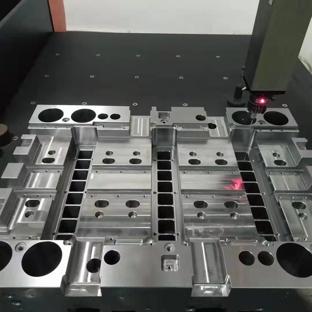
From my professional perspective, the foundation—what we call the **die base**—plays an essential role not only in providing mechanical support but also in maintaining accurate alignment between core and cavity plates during operations. Using inferior or unsuitable materials here would be comparable to building your house on sand—it could look sturdy from above but might collapse over time due to instability underneath.
- Die base serves as a backbone that integrates all molding components
- Proper materials improve heat transfer, dimensional accuracy, and machining stability
- Incorrect base materials can cause premature mold wear or defects in production runs
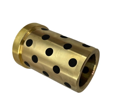
Copper Plate: Why It's Gaining Popularity
In recent years, I've seen more manufacturers turning towards copper plate solutions for die bases. Why? Simple—copper excels in thermal conductivity and durability under harsh molding conditions compared to traditional aluminum or steel alternatives.
I personally started switching some of our critical molds from aluminum to oxygen-free high-conductivity copper (OFHC), and the change has significantly lowered overheating issues, especially in areas with rapid injection cycling. Copper disperses heat faster, meaning fewer warping problems at part ejection and longer die life.
Mold Base: An Overview You Should Understand
A lot of newbies get stuck trying to grasp technical documents that don't explain "what is mould base?". So here’s a real-world description:
If you were casting concrete statues manually, imagine trying without any framework—you’d end up losing form details and consistency with every pour.
The die base works similarly but digitally controlled with CNC machining, ensuring consistent cavity orientation every time the machine operates.
| Base Material Type | Heat Conduction Rate [W/(m·K)] | Relative Hardness [HV] | Machining Difficulty Factor |
|---|---|---|---|
| Steel | 45–80 | 200-700 | Hard — Needs pre-treatments |
| Aluminum Al6061 | ~170–230 | 95 | Semi hard — Requires proper tooling selection |
| Copper C1100 | ~390–425 | 60–80 | Medium to soft – Easier chip management & smoother cuts possible |
- When working with thin rib structures (< 1.2 mm wall thickness) and tight cooling layout designs within the base molding trim section, copper delivers more homogeneous heat removal
Choosing Between OFHC Copper and Brass Alloys for Mold Trimming Applications
Many companies are confused when deciding differences between pure copper grades like C10100 vs brass composites such ZnSn or MnZn blends commonly marketed for “high performance bases."
I tested a few combinations while working on automotive connectors and observed:
| Properties | Use Case Relevance | |
|---|---|---|
| Copper (Pure) | Excellent TC, ductile under tension/compression but lower fatigue resistance than brass under continuous cycle pressure testing | Better suited where rapid dissipation prevents local distortion even if mechanical strain isn't extreme |
| Brass Alloy (E.g. C48500) | Moderate thermal capacity but superior abrasion endurance; prone to galvanic corrosion in damp atmospheres | Favored primarily around ejector mechanisms, where slight hardness adds benefits for repetitive movements without sticking or scoring. |
In essence, use straight-up pure copper plate when thermodynamics matters most and lean into harder alloys like lead-brasses near motion-intensive zones.
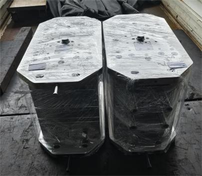
Retrofitting Die Base with Custom-Copper Components: My Process Insights
A few months ago, during one of our mold audits, I identified two critical inserts failing repeatedly due to insufficient material density causing uneven expansion after 200 cycles/day. The problem was not detected by simulation because they didn't simulate copper as backing layer for the main insert blocks originally made in H13 steel with Nitriding layer.
I reconfigured those sections replacing them with electro-deposited laminar bonded oxygen free copper sheet stock which allowed:
- Limited inter-grain movement despite aggressive heating
- Easier integration since the new sheets machined smoothly with less edge chipping than previous beryllium variants (which required protective gear just to clean chips!)
- No additional post weld heat treatment required as original CAD suggested minimal assembly stresses post-mechanical joining technique via silver solder joints
The improvement wasn't subtle either: scrap rates per mold run dropped by nearly 32% inside six weeks—definitely made project ROI discussions very easy later at plant meetings!
Practical Cost-Benefit Analysis from My Workshop
You’re probably wondering whether the added cost is worth this upgrade.
| Mould Section Material | Initial Tooling Material Costs USD/unit | Total Expected Savings During Productive Operation Period | |||
|---|---|---|---|---|---|
| C1100 Copper Plates | $2,625 | (+65%) versus Steel | $4,200 (due to lower rejection + maintenance reduction savings) | +22.65% return on material investment over lifetime | Yes |
From a hands-on operational view—yes. While it’s undeniably more costly up front due to higher commodity prices for metal content, over multiple large batch productions (like >350k units), I see net profit margins growing thanks to reduced rejects, downtime repair and less coolant abuse to combat excess heat spikes.
This decision shouldn't simply be taken based on theory—but real world testing shows clear long-haul value. The challenge becomes selling top management these changes until someone provides actual metrics—and I've found enough case proof from direct implementation logs now!
You may question—can this process ever be standardized? Not quite—there are still tolerances based on application-specific geometry, but what’s crucial is to analyze each job case separately rather than relying only standard shop templates that may overlook opportunities in base construction.
Final Thoughts: Elevating Precision Molding Through Copper Technology Integration
To conclude: If your goal is tighter process tolerance, better energy efficiency during mold cycling AND prolonged equipment usability—seriously rethink what sits under those cavity/core sets.
- Select pure C110 copper for high heat environments and dynamic load regions in base molding trim sections.
- Consider brass alloy hybrid constructions for wear-prone interface regions such guide channels/push rods etc., though ensure galvanic protection is applied against other metals in assembly environment where electrolyte potential exists through moisture/water mist present around water jacket regions during mold maintenance.
- Rely on practical testing instead solely trusting FEA predictions; there's no substitute for real-world behavior validation yet—especially for novel integrations with materials behaving uniquely under cyclic load regimes.
- Track lifecycle costs including maintenance labor / polishing / defect correction—this helps prove copper plate usage brings economic benefit well ahead initial investment outflow timelines perceived in annual budget cycles.
As technology moves toward more integrated mold intelligence and adaptive feedback-controlled presses—the need for thermally robust foundations cannot be ignored, otherwise you'll find the machine chasing errors that root lie far earlier along system structure… specifically inside base design decisions many overlook too early.
My hope is to show the industry needs renewed thinking—not outdated assumptions—when evaluating what lies below every mold cavity block… because in the end... We're shaping quality—from the foundation upward.